HAIGE Machine Tools Introduces a New-Generation Intelligent Bright Bar Finishing Line
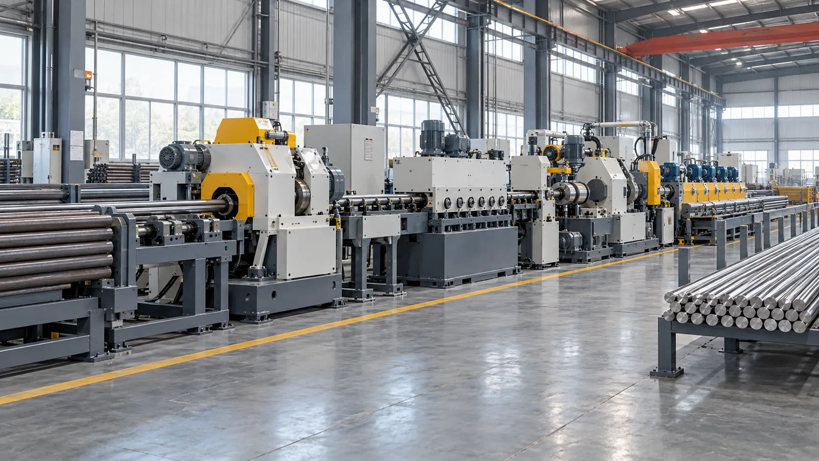
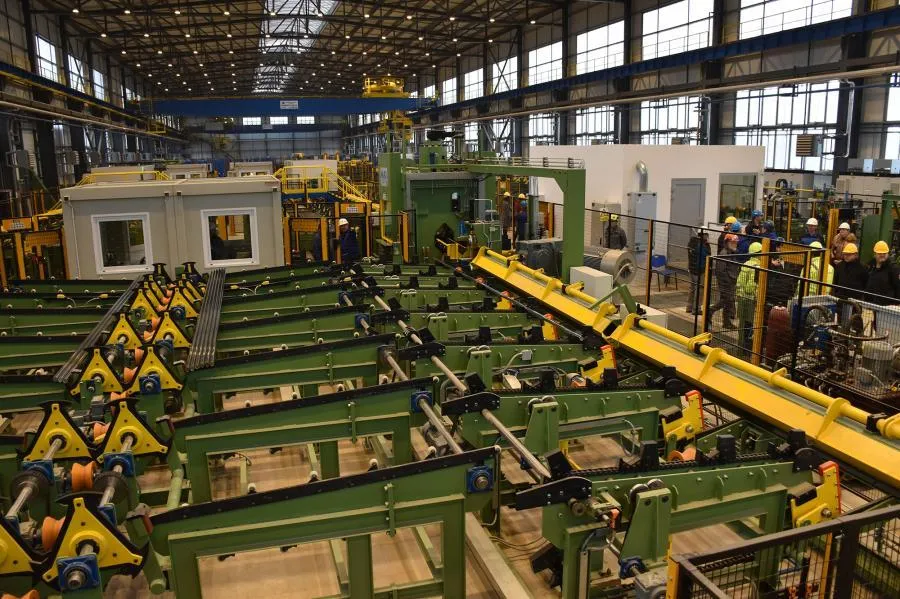
Yantai Haige Machine Tools Co., Ltd. presents intelligent bright bar finishing line solutions for steel producers and metal processors seeking better control of surface condition, dimensional accuracy and bar straightness. The line concept brings together key finishing operations in a coordinated process, with the equipment sequence selected according to incoming material, bar dimensions, production targets and the finished-bar specification.
The company-provided product brief describes a line range covering bar diameters from Ø10 mm to Ø350 mm, with annual production capacity of up to 150,000 tonnes under suitable configurations. Depending on the project, the line can integrate automatic loading, centerless peeling, straightening, polishing, non-destructive testing and other inspection or handling stages. The final machine combination and achievable results depend on the selected configuration, bar material, dimensions, process route and acceptance requirements.
The production line is intended to help steel and metal-processing companies move beyond the sale of untreated black bars toward higher-value bright bar products. Its value lies not in adding every available station to every project, but in combining the processes needed to meet the customer’s dimensional, surface-quality, inspection and output requirements.
An Integrated Process Built Around the Finished Bar
The configuration should begin with the bar the customer needs to deliver, not with a predetermined list of machines. Haige’s complete production line solutions can be considered alongside the individual machines required for each process. Incoming diameter, length, material grade, surface condition, initial straightness and machining allowance determine what each process must achieve. Automatic loading and pre-straightening can prepare the bar for peeling. The bar peeling machine removes a controlled layer from the outside surface to remove scale and certain surface-defect layers while bringing the diameter toward its target. Precision straightening then addresses bar geometry. Grinding or polishing may be added when the finished dimensions or surface roughness require further processing. Inspection, measurement, chamfering and bundling complete the route when they are part of the agreed product specification.
This distinction between individual operations is important when comparing equipment specifications. The maximum diameter of a peeling machine, the best straightness value of a high-precision straightener and the surface-roughness capability of a polishing machine describe different stages. They cannot simply be combined into a promise that every complete line will achieve all of those maximum values simultaneously. The finished result depends on the selected models, material, bar size, machining allowance, process sequence and acceptance method.
Three Bright Bar Finishing Line Configurations
Three configuration levels can be considered during line planning. They are planning examples rather than fixed packages; the final process route should be confirmed against the customer’s material, output specification and production target.
| Configuration | Typical process sequence | Typical planning purpose |
|---|---|---|
| Basic | Loading → pre-straightening → peeling → precision straightening → receiving/unloading | General structural-steel bright bars where the specified result can be achieved without grinding, polishing or NDT stations. |
| Standard | Loading → pre-straightening → peeling → precision straightening → polishing → NDT → receiving/unloading | Alloy-steel and stainless-steel bars where surface finishing and inspection are part of the product specification. |
| High-end | Loading → pre-straightening → peeling → precision straightening → grinding → polishing → NDT → chamfering → automatic bundling | Selected high-precision applications, including some aerospace, automotive and hydraulic bar products, subject to confirmed process and acceptance requirements. |
The basic configuration concentrates on the core steps needed to prepare and peel the bar and then improve its straightness. The standard configuration adds polishing and non-destructive testing, providing additional process stages where surface condition and inspection requirements call for them. The high-end configuration adds grinding and downstream finishing or handling functions for applications that need a more extensive route. These differences are functional: each added station should address a defined product requirement, rather than being included simply to make the line appear more automated.
Line-Level Operating Range: What the Figures Mean
The technical reference table below gives a typical planning range for a bright bar production line. The product-launch brief separately describes a Ø10–350 mm coverage claim. These figures should be reconciled against the actual offered line configuration; they should not be combined into a universal specification. Line-level parameters also differ from the broader maximum ranges of individual machines.
| Line parameter | Indicative value | Technical interpretation |
|---|---|---|
| Incoming bar diameter | Ø15–120 mm; expandable to Ø350 mm | Ø350 mm is an expansion option; confirm which complete-line configuration supports it. |
| Incoming bar length | 3–12 m | Loading, support, transfer and receiving arrangements must suit the actual bar length. |
| Line speed | 8–25 m/min | Depends on the process route and configuration; not every station runs at the same speed. |
| Finished dimensional tolerance | h9–h11; h8 achievable | h8 is possible under suitable conditions, not a blanket guarantee for all materials and sizes. |
| Finished surface roughness | Ra 0.4–1.6 μm | The achievable value depends on the finishing sequence and selected equipment. |
| Finished straightness | ≤0.5 mm/m | Confirm the applicable material, diameter, process and measurement method. |
| Annual production capacity | 30,000–150,000 tonnes/year | Capacity varies with bar specifications and configuration; the upper figure is not universal. |
| Control system | PLC + HMI + MES interface | Confirm sensors, interface scope and integration functions for the quoted configuration. |
High-Precision Targets and Intelligent Production Control
For selected high-precision configurations, the customer-provided product brief identifies targets of h8 dimensional tolerance, surface roughness of Ra ≤ 0.4 μm and straightness of ≤ 0.3 mm/m. These figures describe the stated high-performance target and should be tied to the relevant bar material, diameter, process sequence, machine combination and inspection method. They should not be read as guaranteed results for every line configuration.
The brief also describes intelligent control functions, including PLC-based control, an HMI, online quality monitoring and an MES interface for production-data exchange. Depending on the selected system, online measurement can help operators monitor diameter or straightness during processing. The actual scope of measurement, feedback, automatic compensation and MES integration should be defined in the project specification; an interface alone does not establish that a customer’s MES has already been integrated.
The customer-provided launch template further states that automation can reduce staffing requirements by more than 60% compared with traditional lines. This is a project-level productivity claim and should be used only where the comparison basis, line configuration, operating shift and staffing data are confirmed. The same principle applies to any claim about labor savings or output improvement: it depends on the production process being compared, not solely on the presence of automation.
The diameter figures show why the line-level range must be kept separate from the individual-machine range. The bar peeling machine category has a stated range of Ø5.5–500 mm, with customization possible, while the bright bar line planning range is Ø15–120 mm and may be expanded to Ø350 mm depending on the configuration. A standalone peeling machine may accommodate a wider diameter range than a complete line because straightening, grinding, measurement, transfer and handling equipment must also be sized for the bar. The complete line is limited by the compatible range of the selected stations, not by the largest number in any one machine catalogue.
The annual capacity figure also needs context. The line planning range is 30,000 to 150,000 tonnes per year, depending on bar specifications and configuration. Diameter, bar length, material, machining allowance, process sequence, inspection requirements and product changeover all affect throughput. The upper figure should therefore be presented as a configuration-dependent upper range, not as an output guarantee for every line.
Centerless Peeling: Material Removal, Cutting Depth and Feed Rate
Haige’s bar peeling machines cover a stated diameter range of Ø5.5–500 mm, with customization possible. Feed rates can reach 30 m/min depending on diameter, material, cutting depth and machine model; the listed single-side cutting depth is 0.25–5 mm, and spindle power ranges from 30–250 kW depending on the machine. These are machine-category specifications, not the guaranteed operating range of every model or the speed of a complete production line.
Each figure has a different role in equipment selection. Diameter determines whether the bar can be accommodated. Cutting depth is related to the amount of surface material that must be removed and the remaining target diameter. Feed rate must be assessed together with material grade, diameter, cutting depth, tooling and the required surface result. Spindle power alone does not establish output capacity or finished quality.
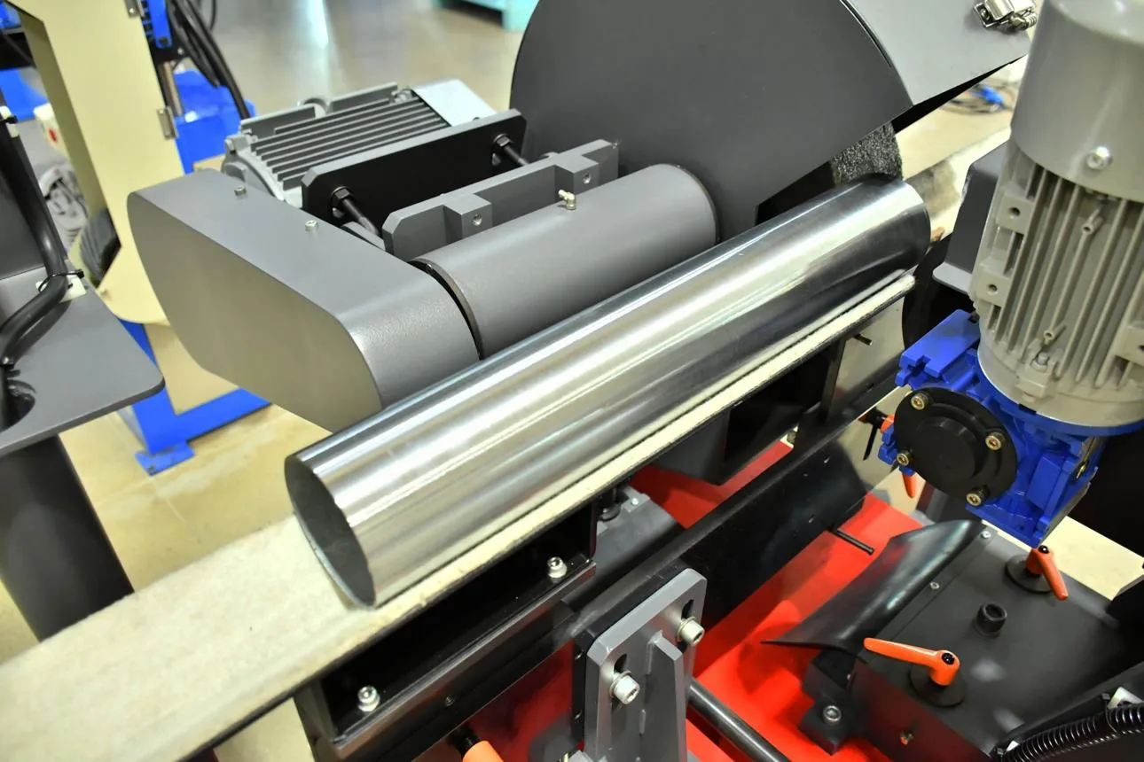
Bar peeling machine configurations may include a rotating cutter head with carbide or ceramic inserts, an automatic centering and guide system, and optional online diameter measurement with automatic compensation. These features can support tool life, bar guidance and dimensional control when they are included in the selected machine. The final technical proposal should state which functions are standard and which are optional for the model being quoted.
Peeling should not be described as a universal substitute for every downstream finishing operation. It removes a controlled amount of surface material and can address scale and certain surface-defect layers, but the finished diameter, straightness and surface roughness still depend on the rest of the process route and the incoming bar condition.
Straightening: Two-Roll and Multi-Roll Machines Are Not Interchangeable
Haige’s straightening machine range includes two-roll and multi-roll designs. The two-roll specifications provided for cover Ø5–160 mm at 10–40 m/min, with post-straightening straightness of 0.3–0.8 mm/m and a high-precision type listed at ≤0.3 mm/m. The multi-roll specifications cover Ø5–200 mm at 10–60 m/min, with a general straightness range of 0.3–1.5 mm/m and a high-precision type also listed at ≤0.3 mm/m.
| Straightener type | Diameter range | Speed | Straightness range |
|---|---|---|---|
| Two-roll straightener | Ø5–160 mm | 10–40 m/min | 0.3–0.8 mm/m; high-precision type ≤0.3 mm/m |
| Multi-roll straightener | Ø5–200 mm | 10–60 m/min | 0.3–1.5 mm/m; high-precision type ≤0.3 mm/m |
These figures describe different machine categories and variants, not a claim that every straightener achieves the same result across the entire diameter range. The appropriate selection depends on bar size, material, incoming curvature and the target straightness. Depending on the model, straightening equipment may use a double-hyperbolic roll design, motorized roll-gap adjustment and optional online straightness measurement with closed-loop feedback. Those features and the stated changeover times should be confirmed for the selected model rather than generalized to every installation.
The stated finished straightness target for the complete line is ≤0.5 mm/m, while a high-precision straightener is listed at ≤0.3 mm/m under suitable conditions. These numbers refer to different levels of the system: a machine’s capability under specified conditions is not the same as a guaranteed result for every completed line. The final line specification should define the applicable bar dimensions, process sequence, measurement method and acceptance conditions.
Grinding and Polishing Serve Different Finishing Goals
Haige’s centerless grinding machines are listed for diameters of Ø3–200 mm, with dimensional accuracy of IT6 grade and above, surface roughness of Ra ≤0.32 μm and cylindricity of ≤0.003 mm. The polishing machine range covers Ø5–250 mm, with a stated polishing speed of 1–4 m/min and surface roughness of Ra ≤0.2 μm; belt polishing, buff polishing and combined methods are available according to equipment type.
| Equipment | Indicative capability | How it should be interpreted |
|---|---|---|
| Centerless grinding machine | Ø3–200 mm; IT6 grade and above; Ra ≤0.32 μm; cylindricity ≤0.003 mm | Machine-level specification; confirm the model and process conditions. |
| Polishing machine | Ø5–250 mm; 1–4 m/min; Ra ≤0.2 μm | Machine-level specification; results depend on material, setup and process conditions. |
These are individual-machine capabilities under the relevant operating conditions. They do not mean that every complete line produces Ra ≤0.2 μm, or that a line running at 8–25 m/min will polish at the same speed. Line speed and polishing-machine speed refer to different contexts and should not be compared as if they were the same measurement.
Grinding may be specified when tighter dimensional control, cylindricity or surface condition is required. Polishing may be specified to improve surface finish. Whether either or both are needed depends on the finished-bar drawing and agreed acceptance criteria. For example, some piston-rod stock intended for chrome plating may require a target of Ra ≤0.2 μm; this application-specific target should not be treated as the standard output of every bright bar line.
For the complete line, the stated finished surface roughness range is Ra 0.4–1.6 μm, while the polishing-machine specification lists Ra ≤0.2 μm. These figures are not interchangeable: the first describes the stated line-level reference range, while the second describes a polishing-machine capability. A line can only be specified to achieve a particular finished roughness when the complete process route and relevant operating conditions support that result.
Inspection and Measurement: Match the Method to the Requirement
Non-destructive testing options include eddy current testing (ECT) and ultrasonic testing (UT). Depending on the selected system, inspection lines may also incorporate automatic sorting, marking and rejection functions. The line process can also include laser-based diameter and length measurement. These functions should be selected according to the material, the defect types of concern, the inspection standard and the production speed.
ECT and UT should not be presented as interchangeable or as proof that every possible defect will be detected. The inspection plan should define what the system is intended to detect, the applicable acceptance criteria and how rejected bars are handled. Where a project requires a specific inspection coverage or detection capability, the relevant equipment specification and validation evidence should be reviewed.
Online diameter and length measurement can collect dimensional information during production. Straightness measurement can be incorporated where bar geometry must be monitored. Automatic compensation and closed-loop feedback are separate functions from measurement alone; the sensors, control logic and adjustment capability must be confirmed for the actual equipment configuration.
PLC, HMI and MES Integration
Depending on the selected equipment and project scope, the control system may include PLC-based centralized control, a touch-screen HMI, stored and recallable parameters, online diameter and straightness measurement, an MES interface, and remote monitoring or diagnostics. These functions can support production data collection and traceability when included in the project scope.
The project specification should distinguish an MES interface from a completed integration with the customer’s system, and distinguish online measurement from automatic closed-loop compensation. The actual sensors, communications, feedback logic and remote-support scope need to be confirmed for the selected configuration. This keeps the description technically meaningful without promising that every feature is standard on every line.
For multi-specification production, parameter storage and recall can help operators manage repeat runs, but the practical benefit depends on how product recipes are defined, verified and maintained. The project specification should identify the control functions required and the level of data exchange expected with any plant-level manufacturing system.
Material Handling, Chamfering and Bundling
A finishing line can also include downstream handling. Chamfering and end-facing equipment can machine bar ends and remove burrs; the stated 6–8 second cycle for simultaneous double-end processing applies only to the relevant equipment configuration and operating conditions. The automatic packaging and bundling system can count, weigh and bundle bars; hexagonal, square and round bundles are listed as options, and MES connectivity can support production-data traceability.
These end-of-line functions matter when the buyer needs a defined delivery format and consistent handling after finishing. The stated chamfering cycle should be confirmed for the actual bar dimensions and equipment arrangement, and the bundling options should be treated as configurable choices rather than assumed standard features. The overall production balance must also account for the cycle times of upstream machining and inspection stations.
Supporting Production Efficiency and Resource Management
For applicable peeling operations, micro-quantity lubrication (MQL) may be considered to reduce cutting-fluid use. Chip collection and briquetting, scrap recovery and noise control can also be evaluated during equipment planning; any quantified recovery or noise figure should be tied to a defined configuration and measurement method.
These environmental figures need to be interpreted in context. MQL suitability depends on the material, tooling and process. Any scrap recovery percentage should be tied to a defined measurement scope and calculation method, while a noise figure should identify the operating condition and measurement method. Without those details, they should be treated as design considerations rather than universal environmental guarantees.
Supporting Higher-Value Bright Bar Production
The company’s product-launch brief positions the line as a way for steel producers and metal processors to upgrade from selling untreated black bars to supplying bright bars with controlled dimensions and surface condition. It estimates a potential increase in value of RMB 800–4,000 per tonne, depending on the product, processing route, market and customer requirements. This figure should be understood as an indicative business-value estimate from the supplied brief, not a guaranteed return for every producer.
The brief attributes the following statement to HAIGE’s general manager:
“Our goal is to help steel and metal-processing companies upgrade from selling black bars to selling bright bars, increasing the added value of each tonne of steel by RMB 800 to RMB 4,000.”
Before publication, the company should confirm that this quotation is approved for public use and that the value-added range accurately reflects the intended claim.
The same supplied brief states that the line has been applied at domestic special-steel companies and overseas projects, and that the product has CE certification and serves markets including Southeast Asia, the Middle East and Europe. These company credentials and market statements should be published only to the extent that the relevant project references and CE documentation cover the line or equipment being promoted. Where the certificate applies to a specific machine or model rather than the complete line, the article should name the applicable scope precisely.
Applications: Configure to the Product, Not Just the Material Name
Bright bar finishing can serve a range of applications, including automotive manufacturing, hydraulic and pneumatic systems, engineering machinery, fasteners, aerospace materials and energy equipment. These applications do not share one universal specification.
For automotive and general engineering uses, the finishing route may be planned around the required diameter, straightness and surface condition. For hydraulic and pneumatic applications, piston-rod stock may require a smoother surface before subsequent treatments; a pre-chrome-plating piston-rod application may specify Ra ≤0.2 μm. Engineering machinery and fastener applications may prioritize dimensional consistency and surface condition according to their product standards.
For aerospace and energy applications, material integrity and inspection requirements may be more demanding, but the exact process and acceptance criteria must be defined by the relevant material and product specification. The presence of a material such as titanium or a nickel-based alloy does not, by itself, establish that a line meets a particular aerospace or energy-sector qualification.
The practical objective is to match the line to the product drawing, production target and inspection plan. Material name alone is not enough to determine the right configuration.
Planning a Bright Bar Finishing Line
Before requesting a quotation, buyers should prepare the material grade, incoming diameter and length, current surface condition, expected production volume, finished dimensional tolerance, target surface roughness, straightness requirement and inspection criteria. Information about the existing process, workshop space, material handling and desired automation level can also help the engineering team assess the required equipment combination.
Yantai Haige Machine Tools Co., Ltd. provides metal finishing machinery and configurable production line solutions for bar, tube and related metal processing applications. Buyers can review Haige’s complete production line solutions, explore the wider metal processing equipment range, or contact Haige to discuss their processing requirements.