CNC Steel Plate Sawing and Milling: Matching Machine to Workpiece
CNC Steel Plate Sawing and Milling: Matching Machine to Workpiece
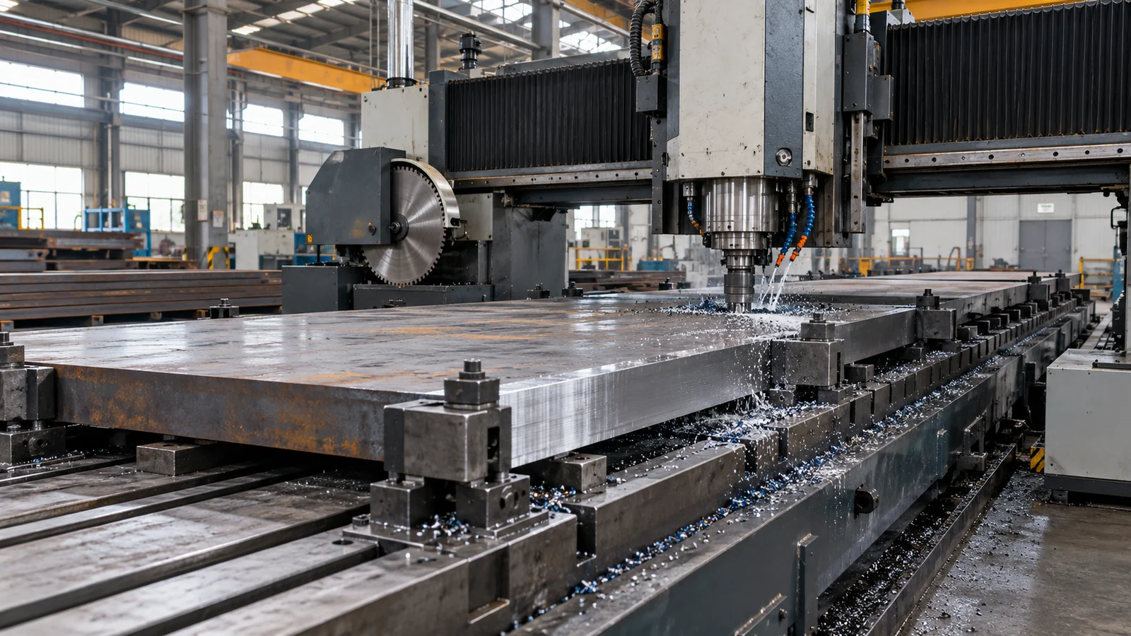
A CNC steel plate sawing and milling machine should be selected against the plates and finished blanks a plant actually needs to produce. Plate dimensions, steel grade, cut direction, required edge condition and downstream machining allowance all affect the suitable configuration. The largest plate that fits on the machine is not necessarily the plate that can be processed to the required tolerance or within the expected production cycle.
HAIGE positions the GKL1310 for strip-plate cutting and preparation of sized plate blanks, while the GKF4500 is intended for long-stroke slitting and sawing of larger plates. Those application directions help narrow the choice, but the final selection should be checked against the current model specification and a representative workpiece.
1. Decide Whether the Job Needs Sawing, Milling or Both
Sawing separates a plate into strips or blanks. Milling removes material with a rotating cutter to create a specified edge or surface. These operations are related but not interchangeable: a straight saw cut is not automatically a milled datum face, and a rough blank dimension is not the same as the final machined dimension.
Before requesting a quotation, mark each drawing with the required output. Identify which edges may remain as-sawn, which edges need milling, and whether the blank will receive further machining. Ask the supplier to confirm the milling tools, operation sequence and included scope for the proposed configuration rather than assuming every job receives both processes simply because “sawing and milling” appears in the machine name.
2. Check the Workpiece Envelope and Model Fit
Compare plate width and thickness with the model’s published sawing range, then check length, mass, clamping access, feed travel and unloading clearance. Longitudinal slitting and cross-cutting can place different demands on machine travel and plate support. Thin strips can be difficult to clamp securely, while large plates can challenge handling and positioning even when their dimensions fall within the nominal range.
| Published model data | GKL1310 | GKF4500 |
|---|---|---|
| Application direction | Strip plates and sized plate blanks | Long-stroke slitting and sawing of large plates |
| Saw blade diameter | Ø425 mm | Ø360 mm |
| Listed plate width range | 600–1,350 mm | 2,000–4,500 mm |
| Listed plate thickness range | 20–100 mm | 20–70 mm |
| Spindle motor power | 15 kW | 15 kW |
| Listed saw-cut surface roughness | ≤ Ra 6.3 | ≤ Ra 6.3 |
| Listed cut perpendicularity | ≤ 0.3 mm/100 mm | ≤ 0.3 mm/100 mm |
| Other listed dimensional data | Parallelism ≤ 0.3 mm/1,000 mm; sawing length tolerance ±0.3 mm | Sawing length tolerance ±0.5 mm |
These are the model figures recorded in the supplied product information, not a substitute for a current, signed technical specification. Confirm the exact configuration, definitions and measurement conditions with HAIGE before using any figure as a contractual acceptance limit. Do not assume the two models share identical travel, feed or accuracy specifications.
3. Specify the Steel Grade and Material Condition
Plates with identical dimensions can cut differently when hardness, material condition or edge condition differs. State the steel grade and whether the plate is hot-rolled, annealed or heat-treated. If the cut path crosses a scaled, flame-cut or otherwise altered edge, include that detail in the request.
Tool choice, feed settings, cooling or lubrication and tool wear should be reviewed against the actual production material. A demonstration on a softer substitute does not validate the process for a harder or otherwise different grade. For mixed-material production, ask which sample grades will be included in the acceptance trial.
4. Separate Blank Dimensions From Finished-Part Requirements
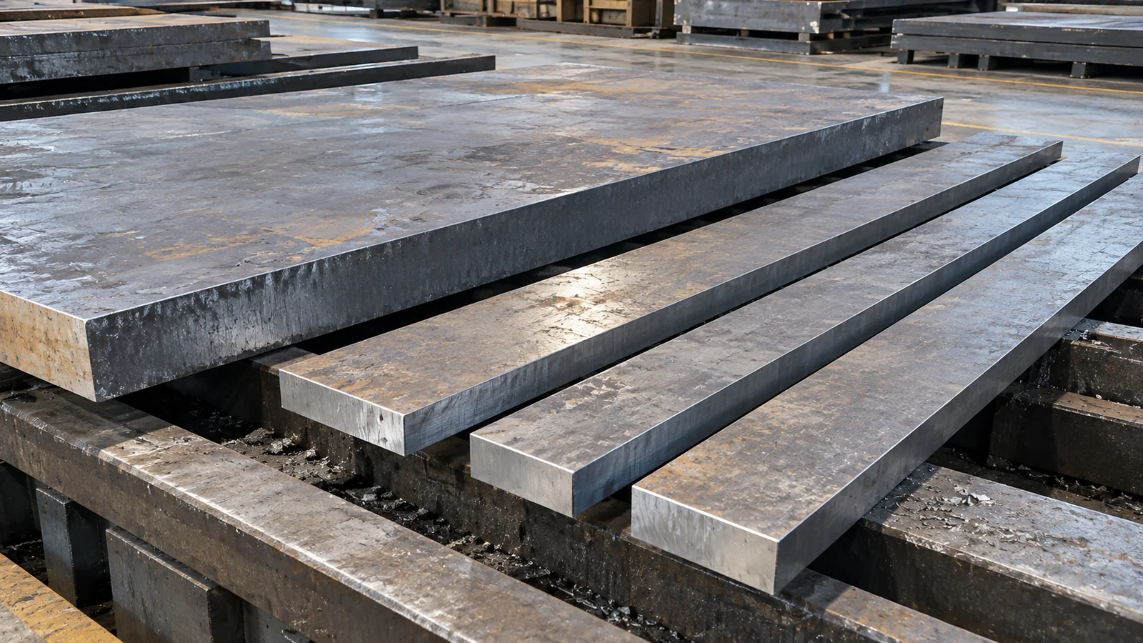
Every cutting plan should distinguish the saw-cut blank from the final component. Saw kerf removes material, and additional stock may be needed for subsequent milling. The required allowance depends on the material, geometry, finishing process and drawing tolerance; it should not be guessed from the machine category.
- Define the nominal dimensions of the saw-cut blank separately from the finished-part dimensions.
- Show cut direction, kerf assumptions and any edge-cleanup allowance on a representative nesting plan.
- Identify which faces or edges are allowed to remain as-sawn.
- Specify the datum, tolerance and inspection method for any milled edge.
- Agree how burrs, offcuts and residual edges will be handled.
5. Evaluate Cut Quality Using Defined Measurements
“CNC accuracy” alone does not describe the quality of a finished blank. Depending on the application, buyers may need to evaluate length tolerance, perpendicularity, parallelism, burr condition, cut-face appearance and repeatability. A roughness value is meaningful only when the measurement method and acceptance conditions are clear.
Agree when measurements will be taken: after sawing, after milling, or after the workpiece has reached a specified inspection condition. Plate support, temperature, chips and clamping can influence the measurement. Use the same datum and measurement method for every sample in the trial.
6. Include Clamping, Support and Material Handling
Machine performance depends on how the plate is positioned and restrained as well as on the saw itself. Review the support bed, clamps, cutting-path clearance, feed movement and outfeed arrangement for the largest plate and the narrowest strip in the production mix. Poor support or movement during cutting can undermine the result even when the CNC positioning system is correctly programmed.
Also check the practical handling sequence: loading, alignment, clamping, cutting, repositioning, unloading, chip removal and inspection. For heavy plates, the required lifting equipment and available floor space should be part of the installation review.
7. Compare Throughput With a Representative Production Cycle
Cutting speed is only one part of throughput. The complete cycle includes material identification, loading, positioning, clamping, cutting, any milling operation, repositioning, unloading and inspection. A supplier’s nominal cutting speed should not be treated as guaranteed finished-blank output for a mixed batch.
To compare proposals fairly, provide the same representative jobs to each supplier and request a breakdown of the cycle. Include the number of cuts, plate dimensions, material grade, any required milling and expected inspection steps. This makes the comparison more useful than comparing machine size or a single speed figure.
8. Define the Acceptance Trial Before Ordering
A practical factory acceptance test should use the specified material grade and condition, representative plate dimensions, the actual cut orientation and agreed inspection points. Include at least one challenging job from normal production rather than selecting only a convenient sample.
- Confirm the rated plate envelope, workpiece mass and installation requirements.
- List the included saw blades, milling tools, fixtures, cooling or lubrication equipment and chip-handling devices.
- Agree on the test material, cut paths, number of repeated cuts and any milling operation.
- Record blank dimensions, cut quality, relevant geometric tolerances and repeatability.
- Document cycle time and clarify operator involvement, tooling changes and handling steps.
Frequently Asked Questions
Can sawing replace all subsequent milling?
Only when the saw-cut result meets every requirement on the drawing. A locating face or edge with a specified finish or datum relationship may still need milling or another finishing operation.
Does a larger machine always produce more parts per hour?
No. Loading, clamping, repositioning, tool changes, the cut path and inspection can have as much influence on the operating cycle as the machine envelope.
How should two CNC plate sawing machines be compared?
Use the same steel grade, plate geometry, cut path, tolerance definitions, support conditions and measurement method in a documented sample test.
Select the Configuration Around the Plate and Finished Blank
Choose the machine only after the workpiece envelope, material condition, cutting path, edge requirements and acceptance criteria are defined. HAIGE’s CNC steel plate sawing and milling machine range provides a starting point for reviewing the GKL1310 and GKF4500 application directions. For a technical review, contact HAIGE with representative drawings, steel grades, plate dimensions, target blank sizes and required inspection criteria.